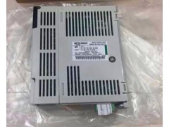
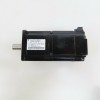
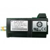
| Model 1: | MDS-B-SVJ2-01 | Model 2: | MDS-B-SVJ2-04 |
|---|---|---|---|
| Condition: | NEW | Voltage/Frequency: | Three-phase AC200 To 230V / 50, 60Hz |
| Tolerable Voltage Fluctuation: | Three-phase AC170 To 253V / 50, 60Hz | Model 3: | MDS-B-SVJ2-03 |
| High Light: |
ac servo pack,ac servo drive |
||
I.Quick detail:
This manual contains points to change and examine when replacing the MDS-A-SVJ Series servo drive unit with the MDS-B-SVJ2 Series servo drive unit. In replacing,also refer to Specifications and Instruction Manual (BNP-B3937).
(Note) The software version of MDS-B-SVJ2 to which this manual (BNP-B2202B) applies is version C0 or later.
II.Features of MDS-B-SVJ2
The MDS-B-SVJ2 Series servo drive unit is for NC,which was developed as the successor model to the
MDS-A-SVJ Series. It has such features as below compared with SVJ.
1. CE Marking compliant (Compliant to European Safety Standard)
2. Installation convertibility with all the capacities of the SVJ series
3. New model, HC motor supported
4. 100,000 pulse ENC supported (OSA104,OSE104)
5. Standard regenerative resistor is integrated in drive unit (All capacities other than 100W)
6. Possible to integrate the battery for the absolute positioning system (MR-BAT) in drive unit (Battery unit
is also possible to use.
7. By wiring the control power supply separately, possible to break the power supply for the main circuit by
contactor
8. New functions added (External observer,overshoot compensation, adoptive filter, etc)
9. Motor brake and contactor control sequence output (DO output)
III.Specification of MDS-B-SVJ2
The specification of MDS-B-SVJ2 is as follows. For detailed specification, refer to Specifications and
Instruction Manual (BNP-B3937).
| Servo drive unit model | SVJ2-01 | SVJ2-03 | SVJ2-04 | SVJ2-06 | SVJ2-07 | SVJ2-10 | SVJ2-20 | |
| Power supply | Voltage/Frequency | Three-phase AC200 to 230V / 50, 60Hz | ||||||
| Tolerable voltage fluctuation | Three-phase AC170 to 253V / 50, 60Hz | |||||||
|
Tolerable frequency
fluctuation
|
Within -/+ 5% | |||||||
| Method |
Sine wave PWM control and current control method
|
|||||||
| Dynamic brake | Built-in | |||||||
| Regenerative resistor |
External
only
|
Built-in or external option | ||||||
| External digital input | External emergency stop input | |||||||
| External digital output | Contactor control output, brake control output | |||||||
| External analog output | -/+ 10V, 2ch | |||||||
| Protection function |
Excessive current break, regenerative excessi
ve voltage break, overload break (Electron
thermal), servo motor excessive heat protecti
on, detector error protection, regeneration
error protection, insufficient voltage and mo
mentary power failure protection, overspeed
protection, excessive error protection
|
|||||||
| Structure |
Protection method: IP20
|
|||||||
| Weight [kg] | 0.7 | 0.7 | 0.7 | 1.1 | 1.5 | 2.0 | 2.0 |
|


