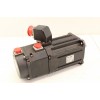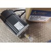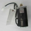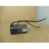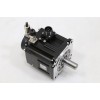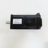

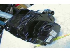
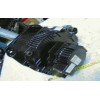


| Brand: | Yaskawa | Model: | SGMDH-32A2A-YR51 |
|---|---|---|---|
| Place Of Origin: | Japan | Type: | AC SERVO MOTOR |
| Power: | 3200W | Volatge: | 200V |
| Current: | 20.9A | Ins: | B |
| High Light: |
ewing machine servo motor,ac servo motor |
||
<1> Remove the jumper when installing an optional DC link choke.
<2> The MC on the input side of the main circuit should open when the thermal relay is triggered.
3.2 Standard Connection Diagram
34 YASKAWA ELECTRIC SIEP C710606 31B YASKAWA AC Drive – J1000 Technical Manual
<3> Self-cooled motors do not require separate cooling fan motor wiring.
<4> Connected using sequence input signal (S1 to S5) from NPN transistor; Default: sink mode (0 V com).
<5> Use only a +24 V internal power supply in sinking mode; the source mode requires an external power supply. Refer to I/O Connections on page 47 <6> Minimum load: 5 Vdc, 10 mA (reference value).
<7> Monitor outputs work with devices such as analog frequency meters, ammeters, voltmeters and wattmeters; they arenot intended for use as a feedback-type of signal.
WARNING! Sudden Movement Hazard. Do not close the wiring for the control circuit unless the multifunction input terminal parameter is
properly set (S5 for 3-Wire; H1-05 = “0”). Improper sequencing of run/stop circuitry could result in death or serious injury from moving equipment.
WARNING! Sudden Movement Hazard. Ensure start/stop and safety circuits are wired properly and in the correct state before energizing the drive. Failure to comply could result in death or serious injury from moving equipment. When programmed for 3-Wire control, a momentary
closure on terminal S1 may cause the drive to start.
WARNING! When 3-Wire sequence is used, set the drive to 3-Wire sequence before wiring the control terminals and ensure parameter b1-17 is set to 0 (drive does not accept a run command at power up (default). If the drive is wired for 3-Wire sequence but set up for 2-Wire
sequence (default) and if parameter b1-17 is set to 1 (drive accepts a Run command at power up), the motor will rotate in reverse direction at power up of the drive and may cause injury.
Figure 3.2 illustrates an example of a 3-Wire sequence.
Type No. Signal Name Description Signal Level
Digital input signals
S1 Forward run/stop command Forward run when CLOSED; stopped when OPEN.
24 Vdc, 8 mA
Photocoupler isolation
S2 Reverse run/stop command Reverse run when CLOSED; stopped when OPEN.
S3 External fault input Fault when CLOSED.
Multi-function digital inputs
Functions set by H1-01 to H1-05.
S4 Fault reset Reset when CLOSED
S5 Multi-step speed reference 1
(Master/auxiliary switch)
Auxiliary frequency reference when CLOSED.
S6 Multi-step speed reference 2 Multi-step setting 2 when CLOSED.
S7 Jog frequency reference Jog frequency when CLOSED.
SN SC Digital input common Refer to Table 2.10 for connection details.
SP Analog input signals
+V +15Vdc power supply +15Vdc power supply for analog inputs or transmitters +15Vdc
(Max. current: 20 mA) A1 Analog input or Speed Command 0 to +10Vdc/100% 0 to +10 V(20 kΩ)
A2 Multi-function analog input 4 to 20 mA/100% 0 to +10Vdc/100% (H3-0
Function set by H3-09.
4 to 20 mA(250Ω)
0 to +10 V(20kΩ)
AC Analog common – –
E(G) Shield wire, optional ground
line connection point – –
Digital output signals M1
During Run (N.O. contact) CLOSED during operation
Multi-function digital output
Function set by
H2-01. Dry contacts
Contact capacity:
1 A max. at 250Vac
1 A max. at 30Vdc
Remote/Auto Operation
(N.O. contact) CLOSED when local control
Multi-function digital output
Function set by M4 H2-02.
Fault output signal (SPDT)
MA/MC: CLOSED during fault condition
MB/MC: OPEN during fault condition
Dry contacts
Contact capacity:
1 A max. at 250Vac
1 A max. at 30Vdc
Analog output signals
FM Multi-function analog output (output frequency)
0 to +10Vdc/100% frequency
Multi-function
analog monitor 1
Function set by H4-01
0 to +10Vdc max. ±5%
2 mA max. AC Analog common –
AM Multi-function analog output (output current) 0 to +10Vdc/100% Drive's rated
output current
Multi-function analog monitor 2
Function set by H4-04 RS-485/ 422 R+ Modbus communication input For 2-wire RS-485, jumper R+ and S+ and jumper R- and S-.
Differential input, R- PHC isolation S+ Modbus communication output
Differential input, S- PHC isolation