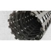
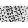
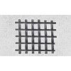
Process:
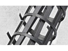
The steel-plastic composite geogrid is composed of high-tensile steel wires with polyethylene (PE) or other components, extruded to form high-strength, anti-pull strips with embossed surfaces and coating.
Steel Plastic Geogrid
Size: 3.95*5
Color: Black
Width: 1-6m
Length: 50-100m
Tensile strength:20kn,30kn,50kn,80kn-200kN/m
Material: HDPE,carbon steel wire
Application: Expressway, railway, soft soil subgrade, retaining wall
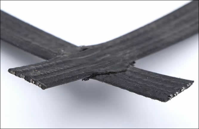
80KN Reinforcement Composite Steel Plastic Geogrid is used for reinforcing rural roads, tensile strength rating of 80KN. It is designed to support the weight of vehicles and provide a more stable driving surface.
High Tenslie Strength Biaxial Welding Steel Plastic Composite Geogrid
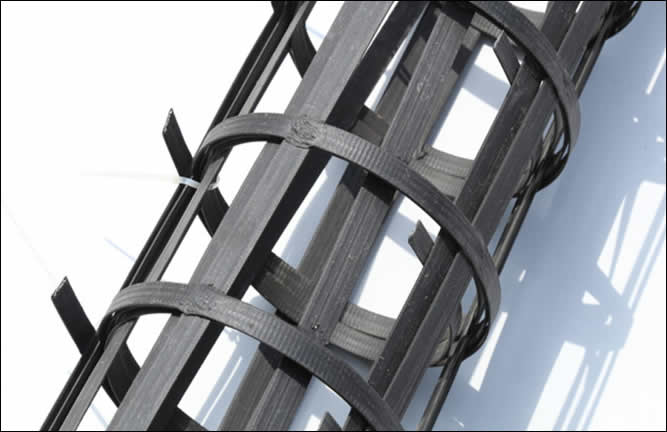
High tensile strength biaxial welding steel plastic composite geogrids are used to reinforce and stabilize the soil in roads, embankments, railways and other ground structures. They provide stability and strength to the foundation soil and reduce maintenance costs.
Classification of Steel-Plastic Composite Geogrid: Uniaxial and Biaxial Bonded-Welded Geogrids.
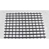
Biaxial steel-plastic geogrid is made with longitudinal and transverse steel-plastic composite ribs as the force-bearing element, welded together with ultrasonic technology. It offers high tensile strength and good integrity, and can be used in a variety of civil engineering projects, such as highways, roads, embankments, bridges, shore protection, flood control, and more. The steel plastic composite consists of high-tensile steel wire, fiberglass yarn, polyethylene (PE), and other components that are specially treated and cooled after squeezing. The embossed surfaces have a rough finish with PE coating.
Characteristics:
1,The tensile force of the steel-plastic composite geogrid is borne by high-strength steel wires woven in warp and weft, providing a high tensile capacity at low strain. The longitudinal and transverse ribs work together to maximize soil body embedment locking. This composite has high strength, low creep, and is adaptable to various environmental soils, making it suitable for tall retaining walls in high-grade highways.
2,The steel wire of the longitudinal and transverse ribs of the steel-plastic composite geogrid is woven into a net, forming a single outer wrapping layer. The steel wire and outer wrapping layer are in coordination, making the damage elongation rate very low (less than 3%). Steel wire is the main force unit of the geogrid, ensuring low creep amount.
3,The steel-plastic composite geogrid has undergone a production process to enhance the roughness of the grating surface and improve the friction coefficient with soil.
4,The width of steel-plastic composite geogrid can reach 6m for economic reinforcement. It improves embedded locking and biting of bearing surface, enhancing the foundation's bearing capacity. It also restrains soil body lateral displacement, boosting foundation stability.
5,The high-density polyethylene used in steel-plastic composite geogrid ensures it won't be eroded by acid, alkali, salt solution or oil at room temperature, and is not affected by water dissolution or microorganisms. Its high-molecular properties are also resistant to aging caused by UV radiation. Longitudinal and transverse ribs of the grating act synergistically when stressed, so no pulling or breaking of the knots occurs. In actual engineering, after compaction of the filler, the grating is not eroded by ultraviolet light and oxygen, and has more strength, strong load-bearing capacity, corrosion resistance, anti-aging, a large friction coefficient, uniform eyelets, easy construction, and a long service life.
Biaxial Steel Plastic Geogrids Parameters
NO. |
Ultimate tensile strength per extended meter-KN/m | Elongation at break % | Ultimate tensile strength per linear meter after 100 freeze-thaw cycles KN/m | Per linear meter after 100 freeze-thaw cycles Elongation at break % | mesh size mm | Frost Resistance Indicator ℃ | Adhesion, solder joints Limit peel force N | |||||
| Longitudinal | Horizontal | Longitudinal | Horizontal | Longitudinal | Horizontal | Longitudinal | Horizontal | Longitudinal | Horizontal | |||
| BWGEO30-30 | 30 | 30 | ≤3 | ≤3 | 30 | 30 | ≤3 | ≤3 | 232 | 232 | -35 | ≥100 |
| BWGEO40-40 | 40 | 40 | ≤3 | ≤3 | 40 | 40 | ≤3 | ≤3 | 149 | 149 | -35 | ≥100 |
| BWGEO50-50(A) | 50 | 50 | ≤3 | ≤3 | 50 | 50 | ≤3 | ≤3 | 220 | 220 | -35 | ≥100 |
| BWGEO50-50(B) | 50 | 50 | ≤3 | ≤3 | 50 | 50 | ≤3 | ≤3 | 125 | 125 | -35 | ≥100 |
| BWGEO60-60(A) | 60 | 60 | ≤3 | ≤3 | 60 | 60 | ≤3 | ≤3 | 170 | 170 | -35 | ≥100 |
| BWGEO60-60(B) | 60 | 60 | ≤3 | ≤3 | 60 | 60 | ≤3 | ≤3 | 107 | 107 | -35 | ≥100 |
| BWGEO70-70 | 70 | 70 | ≤3 | ≤3 | 70 | 70 | ≤3 | ≤3 | 137 | 137 | -35 | ≥100 |
| BWGEO80-80 | 80 | 80 | ≤3 | ≤3 | 80 | 80 | ≤3 | ≤3 | 113 | 113 | -35 | ≥100 |
| BWGEO100-100 | 100 | 100 | ≤3 | ≤3 | 100 | 100 | ≤3 | ≤3 | 95 | 95 | -35 | ≥100 |
| Items | 30-30 | 40-40 | 50-50 | 60-60 | 80-80 | 100-100 | 125-125 | 150-150 | |
| Each linear meter breaking force ≥ | Longitudinal | 30 | 40 | 50 | 60 | 80 | 100 | 125 | 150 |
| Crosswise | 30 | 40 | 50 | 60 | 80 | 100 | 125 | 150 | |
| Yield elongation%≤ | Longitudinal | 3 | |||||||
| Crosswise | 3 | ||||||||
| Breaking force per linear meter KN/m ≥ | Longitudinal | 26 | 32 | 45 | 54 | 87 | 87 | 110 | 130 |
| Crosswise | 26 | 32 | 45 | 54 | 87 | 87 | 110 | 130 | |
| Spot peeling strength N≥ | 30 | ||||||||


